Nuffnang Ads

Wednesday, February 4, 2015

Learn Microcontroller PIC : Lesson 2 - Digital IO + light up LED

Welcome back!!! In microcontroller world, digital IO (IO -Input/ Output) is common. SO what is digital and how the microcontroller know it?

   For common, digital are contain only '0' and '1' digit. In digital world, all the value or data are represented in a string of binary number.
 
So , lets come back. In micronctroller, I use PIC16F877a as an example ( because it was easy for beginner).

That are some common thing you need to know before play(?) with microntroller :
1st : maximun volagte or current supply of the microcontroller *
2nd : the clock fequency (Fosc) of the microntroller *
3rd : the maximum voltage and current sink or source of the microcontroller. *
4th : depend on your application and see datasheet depend what you want to know

For 1 and 3, you can refer to this: (page of 175 in datasheet )

1 :

3:


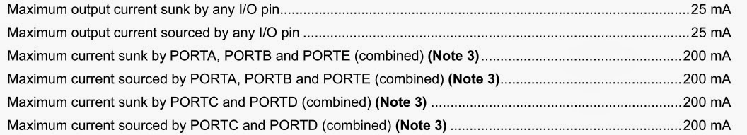
For more info, you can read DC Characteristics in page of 177.

For 2: (why I use 20MHz?)

You can refer to page 176

Ok , from here , you should have a datasheet on your hand computer . Before start, we need to know the pin diagram .
There are common pin we need to connect : Vdd (+5V)  and Vss ( GND ), OSC1 and OSC2, Vpp, PGD, and PGC.

For PGD and PGC , normally is connect to the programmer. In normal application, we are not use it.
For VDD and Vss, also connect to programmer. This 2 pins must connect to power up microcontroller 
For Vpp, if you read datasheet, this pin is active low. Means this pin will will active when it receive '0'. When this pin active, the program in the PIC will restart. 
For OSC1 and OSC2, this 2 pin is connect to crystal (XTAL) and parallel with 2 capacitors.

This is the common connection 


After done connection, lets our start programming (play?).

Lets connect like this:


I will skip the setup MPLABX and its setting. << you are refer to youtube

In PIC microcontroller, major step are same. What same ? Lets find out it.

The step is setting of the PIC.
This tutorial is for MPLABX :

This is a sample code :

#include <xc.h> // library
#define _XTAL_FREQ 20000000
// CONFIG
#pragma config FOSC = HS        // Oscillator Selection bits (HS oscillator)
#pragma config WDTE = OFF       // Watchdog Timer Enable bit (WDT disabled)
#pragma config PWRTE = ON       // Power-up Timer Enable bit (PWRT enabled)
#pragma config BOREN = OFF      // Brown-out Reset Enable bit (BOR disabled)
#pragma config LVP = OFF        // Low-Voltage (Single-Supply) In-Circuit Serial Programming Enable bit (RB3 is digital I/O, HV on MCLR must be used for programming)
#pragma config CPD = OFF        // Data EEPROM Memory Code Protection bit (Data EEPROM code protection off)
#pragma config WRT = OFF        // Flash Program Memory Write Enable bits (Write protection off; all program memory may be written to by EECON control)
#pragma config CP = OFF         // Flash Program Memory Code Protection bit (Code protection off)

void main()
{
    TRISD = 0;
    RD1 = 1;
    while (1);
}
//end

In the code :

void main()
{
    TRISD = 0;
    RD1 = 1;
    while (1);
}

TRIS is to set the electron flow direction of PORT
TRISD mean is to set the PORTD as input(1) or output(0) . Input mean 'read' from the PORTD , Output mean 'write' to PORTD. For this case, we set TRISD as 0 (output).

Next step is set which pin as output. If you refer to pin diagram, the PORTD have 8 pin ( RD0 to RD7). You can set any pin (from RD0 to RD7 ). For this case, we set RD1 as 1(output).

From here, you may confuse, why both value is same but why the result is different?

For TRISD and PORTD , you can see this : 

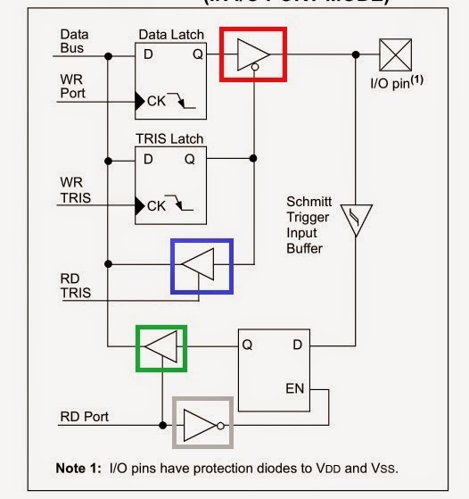
When you set TRISD as 0, the RD TRIS (the tristate logic) is off (the blue square) and the TRIS in read square is on . Next , you set PORT (RD1 = 1) as 1 , the TRIS in grey square is off, and the TRIS in green square is on. As long TRIS in red square is on, all the value from Data Bus is send to IO pin.

To have a easy look :

TRIS                output
Red square:         on 
Blue square :       off   
Green square :    on    
Grey square       off    

From here , you are able to start program by using simple IO pin (actually O only )

So have a nice day


Tuesday, February 3, 2015

Your own programming socket

Remember last post, I say this " Or you can build your own one"? Ya, this post is talk about this how to build it..  but what is that? So is this:

Ok , what that? This is to replace the this : 

This is programming socket (maybe have other name ). SO how to build it?

First this is the material you need :
1) Stripboard
2) Some wire (at least 7 cm or depend on you)
3) programming socket (10 pin)

4) Solidering gun and soldering lead
5) cutting tool

Now let we start build : 
1) Cut your donutboard into 6X6 (or larger size )  
like this : for me, use 6X5

2) place programming socket like this
(behind)
(in front)

3 ) if the position ok for you, let start solder wire to it. 
4 ) First reference to this 

5) Then from here , choose 5 wire .You can use difference colour ,so that you can differentiate it easy , or you can use all same colour wire but with its label (Vpp , PGC, PGD, VDD and GND) . From here, we are not using Aux_Out and GND is connect together. 

6) After choose your wire, and the soldering gun are ready to use. You can start to build ... 
7) Before that, please cut off the connection here . So that, they are independent 
like this : (the red line)

8) Solder the programming socket into stripboard, make sure all the pin is solder and not to connect each other. After that, see this (similar as yours when you flip it?)
behind
in front
         
From here, you can refer to the this 

After refer , start solder with wire : for me this is the following colour
 - red : Vdd (pin 8)
 - black : GND  (pin 4 and pin 6)
 - green : Vpp (pin 3)
 - brown : PGD (pin 7)
 - white : PGC (pin 5)

Solder all wire except for GND. After you done, connect the pin 4 and pin 6 with soldering lead, then connect with its wire (black). 

From here, you are done to build your own programming socket with connector.

So, have a nice day.


Monday, January 19, 2015

Learn Microcontroller PIC : Lesson 1 - Introduction to PIC

If you are new to microcontroller, that not the problem . Because this will guide you how to use it. 

So, What is microcontroller? To answer this, you may see this link : microcontroller (from wikipedia) or you also can find it in other sources. For me, understand what is microcontroller is important but not its history because we are focus on the its application.

Now, I introduce PIC microconroller ,PIC (from wikipedia). 

Before start, we need some components:
HARDWARE :
1) 1 - PIC16F877A
2) 2 - 33pF Ceramic Capacitor
3) 1 - 10k ohm resistor (0.25W)
4) 1 - 20MHz crystal 
5) 1 - PICKIT2 (Uic00b programmer)
6) 1 - Breadboard 
7) 1 - LED (any colour but with low current)(tips : not ultra bright LED or big size LED)
8) 1 - 1k ohm resistor (0.25W)
9) Multimeter (optional)
10) some wire (single core) --> 

SOFTWARE :
1) MPLAB or MPLABX 

Ok, when you prepare all the material. You are ready to start learn.

Procedure :

Connect the circuit as show in the below :


#Important : The MCLR pin is a pin to reset (Hardware reset)  the program in the PIC. The PIC will reset when the MCLR pin receive '0' or GND.
After you connect the circuit, let we install MPLAB or MPLABX. The installation tutorial for MPLAB or MPLABX  . The installation will take some time. 

When you done install, you can start to program the PIC . Before that, are we forgot something? Erh ......... Oh ya ... how to connect programmer to PIC? Ok, this can refer to the datasheet of the UIC00b programmer. To solve this, first we need to know what pin should we need to connect? According to the datasheet of the UIC00b page 7. 
From the picture above, that are 6 pin are used which is pin 3, 4, 5, 6, 7, 8, 9. But for our application, pin 9 is unused. If you are not good on soldering , you may can buy this :

 Or you can build your own one . This I will teach you later (maybe in next post) .

When you are connect the UIC00b programmer to your circuit and plug in the USB to your computer. Now you can start program. First , you can follow this tutorial (MPLAB) or (MPLABX).

At here, you may know how to program PIC to light up a LED.

This is the program :

#include <htc.h>
#define _XTAL_FREQ 20000000 // tell PIC the value of the crystal
__CONFIG(0x3F32); // configuration bits

void main() // main program
{
TRISD = 0; //this is to set the pin direction : 0 for output , 1 for input 
RD1 = 1; // this is to set the pin : to light up LED
while (1); // this is must because the PIC program is infinite loop
}

From here, you should know how to program PIC and its basic connection. And have a nice day.

Friday, January 16, 2015

Small project


在这我分享一下,我之前的小小的project:

Component 如下:
PIC18F4550, crystal(20Mhz) , capacitor(2X 33pF)
- 2 set of IR(LED) 
LM324
- Speaker (8 ohm)
- 一些resistor (0.25W 够了)
- 2 X LED (任何颜色)

连接如图:


这是coding:

CONFIG FOSC=HS
;CONFIG WDT=OFF
LIST P=18F4550         ; the microcontroller that this program is written for
LIST F=INHX8M          ; the file format chosen

#include P18F4550.INC   ; the included file contains all SFR definitions and more
a0  equ 0x00
a1  equ 0x01
        org 0h
        goto    main
        org 50h
main    clrf    TRISD
        setf    TRISC
        bsf     PORTD,7;power on
        bcf     PORTD,4;off speaker led
        bsf     TRISA,0
        movlw   0x0B
        movwf   a1
        btfss   PORTC,0
        call    speaker
        bra     main
speaker;speaker function
        btg     PORTD,0
        bsf     PORTD,4;on speaker led
        call    adcf
        call    ADCc
        call    TSf
        movff   ADRESL,a0
        btfsc   PORTC,0
        return
        bra     speaker
T0f     ;timer 0 = 10us
        movlw   0xFF
        movwf   TMR0H
        movlw   0xCE
        movwf   TMR0L
        movlw   0x88
        movwf   T0CON
        goto    T0P1
T0P1    btfss   INTCON,TMR0IF
        bra     T0P1
        bcf     INTCON,TMR0IF
        return
TSf     ;timer produce due to adc value(max=255)
        call    T0f
        decf    a0
        bnz     TSf
        return
adcf    ;adc init
        movlw   0x03
        movwf   ADCON0
        movlw   0x0E
        movwf   ADCON1
        movlw   0x88
        movwf   ADCON2
        return
ADCc    btfsc   ADCON0,1
        bra     ADCc
        bcf     PIR1,6 
        return
        end


我只是用Timer,ADC和PWM而已。

如何function:
1)接进LM324的IR是为了模仿on-off switch的功能。
2)接进PIC(ADC pin)的IR是要读取它的analogue的data。我用的ADC bit size 是8bit(是可以自己set的)。之后,我把它的data 放进timer function。根据它的data,convert 成delay time。ADC value 越低,frequency越高。